
CONTROL OF FIXED SHUNT REACTORS

Generally, Fixed Shunt Reactors are designed and located in a way to be connected to the network most of the time. However, lately it is often required by the electrical utilities to perform automatic switching in/out operations on Switchable Fixed Shunt Reactors by monitoring the bus-bar voltage level. Figure 8-1 illustrates a typical Switchable Fixed Shunt Reactor control scheme.
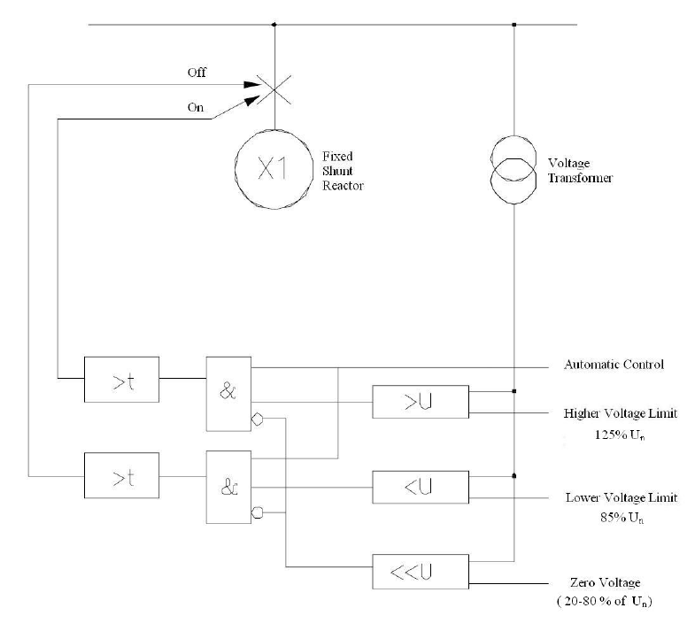
Figure 8-1: Typical On/Off switching control of a Fixed Shunt Reactor
As seen in Figure 8-1, the normal operating range is 85% to 125% of bus-bar nominal voltage. For voltages higher than 125% of the nominal voltage, the switch-in (On) command is issued. Likewise, for voltages lower than 85% of the nominal voltage, the switch-out (Off) command is issued. This control system is interlocked with a zero voltage detection which is considered as voltages very lower than 20-80% of the nominal voltage; in this case, the bus-bar will be assumed dead and the control function will be blocked. As shown, this switching function is delayed in order to ensure that the voltage change in network is stable. The aforementioned functionality is quite easy to integrate into multi-functional numerical relays. 

Moreover, the shunt reactors are generally designed for natural cooling with the radiators mounted directly on the tank. However, sometimes it is required to have some control action on the cooling circuit depending on the status of the shunt reactor circuit breaker. The control action can be initiated by either the circuit breaker auxiliary contact or the operation of an Over-Current relay which is set to 50% of the reactor rated current. By using Over-Current relay, more secure control action is achieved when Shunt Reactor is energized regardless of the circuit breaker auxiliary contact status.

Comments

Popular posts from this blog

PRIMARY SECONDARY AND TERTIARY FREQUENCY CONTROL IN POWER SYSTEMS

Primary, Secondary and Tertiary Frequency Control in Power Systems Author: Engr. Aneel Kumar Keywords: frequency control, primary frequency control, automatic generation control (AGC), tertiary control, load-frequency control, grid stability. Frequency control keeps the power grid stable by balancing generation and load. When generation and demand drift apart, system frequency moves away from its nominal value (50 or 60 Hz). Grids rely on three hierarchical control layers — Primary , Secondary (AGC), and Tertiary — to arrest frequency deviation, restore the set-point and optimize generation dispatch. Related: Power System Stability — causes & mitigation Overview of primary, secondary and tertiary frequency control in power systems. ⚡ Primary Frequency Control (Droop Control) Primary control is a fast, local response implemented by generator governors (dro...

CASCADED TRANSFORMERS METHOD FOR GENERATING AC HIGH VOLTAGE

High-Frequency AC High Voltage Generation Using Cascaded Transformers Author: Engr. Aneel Kumar Figure 1: Infographic representation of cascaded transformers method for generating high AC voltages. Introduction In high voltage engineering , generating very high alternating current (AC) voltages is essential for testing equipment like insulators, circuit breakers, power cables, and other apparatus. One common and effective method for producing such voltages is the cascaded transformers method . This technique uses a series connection of specially designed test transformers , where the secondary of one transformer feeds the primary of the next. In this way, voltages are built up step by step, achieving levels in the range of hundreds of kilovolts (kV) or even megavolts (MV). Working Principle The principle of cascaded connection relies on the fact that each...

Advantages of Per Unit System in Power System Analysis | Electrical Engineering

  Advantages of Per Unit System in Power System Analysis In electrical power engineering, the per unit (p.u.) system is one of the most widely used techniques for analyzing and modeling power systems. It is a method of expressing electrical quantities — such as voltage, current, power, and impedance — as fractions of chosen base values rather than their actual numerical magnitudes. This normalization technique provides a universal language for system calculations, minimizing errors, simplifying transformer modeling, and enabling consistency across multiple voltage levels. Because of these benefits, the per unit system is essential in fault analysis, load flow studies, transformer testing, and short-circuit calculations . ⚡ What is the Per Unit System? The per unit system is defined as: Q u a n t i t y ( p u ) = A c t u a l   V a l u e B a s e   V a l u e Quantity_{(pu)} = \dfrac{Actual \ Value}{Base \ Value} Q u an t i t y ( p u ) ​ = B a se   ...

ADVANTAGES OF INTERCONNECTED GRID SYSTEM

Interconnected Grid System: Working, Advantages, Disadvantages, and Comparison with Isolated Grids Author: Engr. Aneel Kumar Figure 1: Infographic showing key advantages of an interconnected grid system. Introduction An interconnected grid system refers to a network of multiple power generation sources, transmission lines, substations, and distribution systems that are linked across regions, states, or even countries. Unlike an isolated grid (or islanded grid) which operates independently, an interconnected grid allows electricity to flow between interconnected nodes, enabling numerous benefits and some trade-offs. In today’s energy landscape—where demand, renewable generation, reliability, and cost pressure are all increasing—understanding how an interconnected grid works, what factors are essential, and what its advantages and disadvantages are is critical for utility planners, reg...

CLASSIFICATION OF POWER SYSTEM BUSES

Each bus in the system has four variables: voltage magnitude, voltage angle, real power and reactive power. During the operation of the power system, each bus has two known variables and two unknowns. Generally, the bus must be classified as one of the following bus types: 1. SLACK OR SWING BUS This bus is considered as the reference bus. It must be connected to a generator of high rating relative to the other generators. During the operation, the voltage of this bus is always specified and remains constant in magnitude and angle. In addition to the generation assigned to it according to economic operation, this bus is responsible for supplying the losses of the system. 2. GENERATOR OR VOLTAGE CONTROLLED BUS During the operation the voltage magnitude at this the bus is kept constant. Also, the active power supplied is kept constant at the value that satisfies the economic operation of the system. Most probably, this bus is connected to a generator where the voltage i...

AC Transmission Line and Reactive Power Compensation: A Detailed Overview

  Introduction The efficient operation of modern power systems depends significantly on the management of AC transmission lines and reactive power. Reactive power compensation is a vital technique for maintaining voltage stability, improving power transfer capability, and reducing system losses. This article explores the principles of AC transmission lines, the need for reactive power compensation, and its benefits in power systems. Keywords: Reactive Power Compensation Benefits, STATCOM vs SVC Efficiency, Power Transmission Stability Solutions, Voltage Stability in Long-Distance Grids, Dynamic Reactive Power Compensation.      Fundamentals of AC Transmission Lines AC transmission lines are the backbone of modern power systems, connecting generation stations to distribution networks. They have distributed electrical parameters such as resistance ( R R R ), inductance ( L L ), capacitance ( C C ), and conductance ( G G ) along their length. These parameters influence ...

REVERSING DIRECTION OF ROTATION OF UNIVERSAL MOTOR

The direction of rotation of a universal motor can be changed by either: (i) Reversing the field connection with respect to those of armature; or (ii) By using two field windings wound on the core in opposite directions so that the one connected in series with armature gives clockwise rotation, while the other in series with the armature gives counterclockwise rotation. The second method, i.e, the two field method is used in applications such as motor operated rheostats and servo systems. This method has somewhat simpler connections than the first method. For simple applications like portable drills etc. manual switches are frequently used for reversing the direction of rotation of the motor. Figure  1 (a and b) shows how a DPDT (Double Pole Double Throw) switch and a three position switch may be used for reversing the direction of rotation of single field and double field type of motors respectively. Figure 1 Reversing of a universal motor (a) Armature re...